


Design and Application of MEMS Magnetic Sensors in Preparation Process
2021-05-02
0 Preface
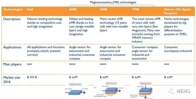
Magnetic sensor technology classification (Source: "Magnetic Sensor Market and Technology - 2017 Edition")
Because magnetic sensing technology is not affected by dust, dirt, grease, vibration, and humidity, magnetic sensors have a wide range of applications in industrial equipment and electronic instruments, such as magnetic resonance imaging, automatic production control, process industries, coal mining exploration , current measurement, defect location, and residual stress detection of ferromagnetic materials. In order to meet the requirements of different applications, corresponding magnetic sensors have been prepared based on different sensing principles. Common SQUIDs, fluxgate magnetometers, Hall effect sensors, and anisotropic magnetoresistive magnets (AMRs) have been used. Sensors, microelectromechanical systems (MEMS) magnetic sensors.
In these sensors, although the SQUID can detect very small magnetic induction (fT), the device needs low-temperature cooling and is susceptible to electromagnetic interference. This requires complicated peripheral devices; the fluxgate magnetometer has a large size and consumes large power. The small operating range and the inability to detect the characteristics of the static magnetic field limit its application; Hall effect sensors show that increasing the sensitivity requires increased power consumption; and AMR sensors require the deposition of magnetic materials and an automatic correction system, and are easy to appear in a few mT. Saturation; Because MEMS technology can reduce the size of traditional magnetic sensors, MEMS-based magnetic sensors have the advantages of small size, high performance, low cost, low power consumption, high sensitivity and mass production, and their preparation materials are dominated by Si. Eliminating the magnetic sensor preparation must use special magnetic materials and its effect on the measured magnetic field.
In this paper, the main design, fabrication, sensing technology and device properties involved in the preparation of MEMS-based magnetic sensors are reviewed, and their future development is forecasted.

Magnetic Sensor Market (Source: "Magnetic Sensor Market and Technology - 2017 Edition")
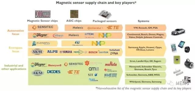
Magnetic Sensor Supply Chain and Key Manufacturers (Source: Magnetic Sensor Market & Technology - 2017 Edition)
1, MEMS magnetic sensor design and production
1.1 MEMS Magnetic Sensor Design
In order to obtain a high-performance MEMS magnetic sensor, it is first necessary to design the device according to the application object of the device, thereby determining the structure of the device, the materials used, the working principle of the application, and the induction technology. MEMS designers can choose the best process and materials for manufacturing sensors based on simulation and modeling tools, and predict the performance of MEMS magnetic sensors. At the same time, designers must consider the rules of material growth, device fabrication, signal modulation, and induction technology that should be followed during device fabrication to avoid errors that affect sensor performance. When developers use MEMS sensors, the following points must be considered: optimizing device structure design; packaging design; reliable material properties and standard manufacturing processes; suitable design and simulation tools; reducing electronic noise and parasitic capacitance; reliable signal processing systems; Reliable testing.
Currently used MEMS design tools include MEMSCAP, CoventorWare, IntelliSuite, and Sandia Ultra-planar Multi-level MEMS Technology (SUMMiTV). These design tools have modules for creating sensor layouts and checking design rules, and can simulate the steps of the micromachining process, helping to reduce the time required to obtain high-performance MEMS magnetic sensors.
1.2 MEMS magnetic sensor production
In general, the manufacture of MEMS magnetic field sensors can be implemented using bulk or surface micromachining processes. Since silicon has very good mechanical and electrical properties, it is used as its main processing material. For example, silicon has a minimum mechanical hysteresis and a fracture stress of approximately 1 GPa. In addition, the electrical properties of silicon can be significantly improved after phosphorus or boron doping.
The bulk micromachining process uses wet and dry etching techniques to prepare the desired material structure by isotropic and anisotropic etching of the material. The surface micromachining process is the fabrication of MEMS devices by depositing, patterning, and etching different layers of material on the substrate. Typically, these layers are used as structures and sacrificial layers. Figure 1 shows the SEM of a magnetic sensor prepared by the body processing and surface micromachining processes, respectively.

Figure 1 SEM obtained by body processing and surface processing
2. Sensing Technology and MEMS Magnetic Sensors
2.1 Sensor Technology
MEMS magnetic sensors, such as piezoresistive, capacitive, and optical technologies, can be fabricated using different sensing technologies. These techniques can convert magnetic field signals into electrical or optical signals, respectively. In the electrical signal detection, when the power is limited or there is strong electromagnetic interference, its application will be affected. The optical signal detection is more advantageous than the electrical signal detection under the conditions of strong electromagnetic fields and long-distance transmission, so it is often used in extreme situations. In addition, in order to obtain high resolution and sensitivity, MEMS magnetic sensors require a signal modulation system with low electronic noise and parasitic capacitance.
2.2 Various MEMS Magnetic Sensors
V. Kumar et al. reported that the Lorenz force resonant MEMS magnetometer realized by the internal thermal piezoresistive oscillation amplifier has extremely high sensitivity. They used a bias current tuning method to increase the effective quality factor of the resonator from 680 to 1.14x10^6, which has proven to increase the internal amplification factor by 1620 times. In addition, in addition to improving the quality factor of the device, the resonator bias current increases the sensitivity of the device by 2400 times (from 0.9 μV·nT^(-1) to 2.107 mV·nT^(-1)). When the DC bias current is 7.245 mA, the maximum sensitivity is 2.107 mV·nT^(-1), and the noise floor is 2.8 pT·Hz^(-1/2).
E. Mehdizadeh et al. reported on a MEMS magnetic sensor fabricated on a low resistivity n-type SOI substrate based on Lorentz force. The SEM and electrical connections of the main components are shown in FIG. 2 respectively. The sensor utilizes a dual-plate silicon resonator (thickness 10 μm, one of which has a gold wire of 10 μm x 200 nm), where two narrow beams are designed to connect with two Si plates; when the resonator is in plane vibration mode When it oscillates, it undergoes cyclical tensile and compressive stresses and therefore exhibits piezoresistive properties. The quality factor of harmonic resonators is amplified at atmospheric pressure (from 1140 to 16900). In addition, the sensor can increase its sensitivity by increasing the vibration amplitude of the resonator. In air, when the resonance frequency is 2.6 MHz and the quality factor is 16900, the sensor sensitivity is 262 mV/T.

Figure 2 SEM and electrical connections of the main components of a piezoresistive MEMS magnetic sensor
AL Herrera-May et al. prepared a MEMS magnetic sensor with a simple resonator and a linear electrical response. It consists of a perforated plate (472 μm x 300 μm x 15 μm), 4 bending beams (18 μm x 15 μm x 15 μm), 2 support beams (60 μm x 36 μm x 15 μm) and 4 p-type pressure sensitive The resistance formed by the Wheatstone bridge is shown in Figure 3. Fabricating the device on a SOI substrate using a standard bulk micromachining process, controlling the dynamic range of the device by adjusting the excitation current to maintain a linear electrical response, obtaining a device quality factor of 419. 6, a sensitivity of 230 mV·T, and a resolution of 2. 5 μT, power consumption is 12 mW. The sensor is suitable for non-destructive magnetic testing and detection of ferromagnetic material defects and corrosion.
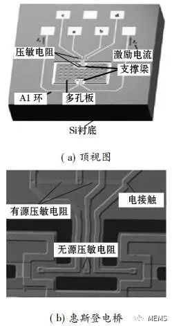
Figure 3 Top view of the main part of a MEMS magnetic sensor and a Wheatstone bridge consisting of four varistors
Langfelder et al. prepared a MEMS magnetic field sensor with a capacitive readout that can detect the magnetic field perpendicular to the surface of the resonant structure (z axis). It consists of a set of fixed stators and two fine beam suspended shuttles, forming two differential parallel plate sensitive capacitors C1 and C2, see Figure 4. The beam with the resonant frequency of the sensor interacts with the magnetic field when there is a current, so that the two thin beams receive the Lorentz force. This force is perpendicular to the plane formed by the magnetic field and the alternating current, resulting in a displacement of the beam and the parallel plate, which can be detected by a change in the differential capacitance. The sensor has a total sensitivity of 150 μV·μT^(-1) at a peak drive current of 250 μA, a theoretical noise of 557. 2 μV·Hz^(-1/2), and a resolution of 520 nT·mA^(- 1) Hz^(-1/2), quality factor about 328, resonance frequency 28.3 kHz.
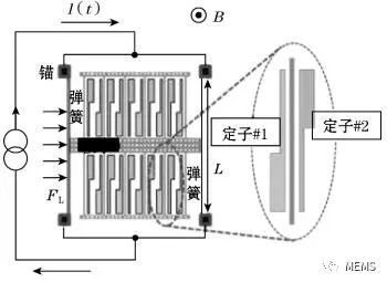
Fig. 4 Schematic diagram of a MEMS magnetic field sensor formed by a shuttle supported by parallel plates, a fixed stator, and two thin beams
M. Li et al. designed a magnetic field sensor composed of a bending beam resonator (1200 μm x 680 μm x 40 μm). The bending beam resonator is coupled with the current-carrying Si beam by a micro-lever mechanism, and the resonator is electrostatically and capacitively induced by means of 30 interdigitated electrodes on each side of the bending beam, and the sensitivity of the sensor is 6687 ppm·mA^( -1)·T^(-1), quality factor 540, resonance frequency 21.9 kHz (1 ppm = 10^(-6)).
Aditi et al. prepared MEMS magnetic field sensors by using anodic bonding technology of SOI and glass sheets. The device fabrication process has the following advantages: low temperature (≤ 400 °C), reliable, repeatable, few photolithography steps and the ability to control the distance between electrodes. The power consumption of the sensor is 0.45 mW and the resolution is 215 nT·Hz^(-1/2).
B. Park et al. designed a magnetic field sensor composed of a silicon resonator and a compact laser positioning system, as shown in Fig. 5. The system has photodetectors and laser diodes for monitoring current-biased mirror angular displacement. The resonator consists of a silicon film (3000 μm x 3000 μm x 12 μm) coated with an aluminium layer (2500 μm x 2500 μm x 0.8 μm) supported by two torsion springs (2100 μm x 100 μm x 12 μm) An aluminum wire having a width of 30 μm and a thickness of 0.8 μm was deposited thereon. The applied magnetic field is related to the displacement of the reverse mirror. When the coil bias current is 50 mA, the sensor's sensitivity is 62 mV·μT^(-1), the resonant frequency is 364 Hz, and the quality factor is 116, 53 mHz. The resolution is 0.4 nT and the noise floor is 1.78 nT·Hz^(-1/2).
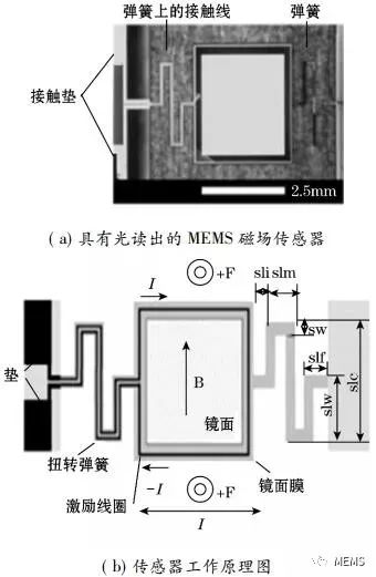
Figure 5 Schematic diagram of a MEMS magnetic field sensor and sensor with optical readout
M. Lara-Castro et al. proposed a portable signal modulation system for a MEMS magnetic field sensor implemented on a printed circuit board equipped with two sinusoidal signal generators capable of resonant magnetic field sensors. The magnetic field sensor consists of a Wheatstone bridge consisting of a resonant silicon structure (600 μm x 700 μm x 5 μm), an aluminum ring (1 μm thick) and four p-type varistors. The two signal generators have a frequency stability of ±100 ppm and a resolution of 1 Hz. In this system, the magnetic field and voltage have an approximately linear relationship; the sensitivity and resolution at atmospheric pressure are 0.32 V/T and 35 nT, respectively.
Long Liang and others used MEMS magnetic torsion pendulums and differential capacitors to form MEMS magnetic sensors. The magnetic torsion pendulum is obtained by forming a CoNiMnP permanent magnet film on a silicon film of a double-end fixed beam. The size of the magnetic sensor is 3.7 mm x 2.7 mm x 0.5 mm, and the prepared MEMS magnetic sensor has a good linearity with a sensitivity of 27.7 fF/mT. The minimum resolvable magnetic field size is 36 nT.
3. Outlook
Current Lorentz force-based MEMS resonant magnetic sensors detect magnetic fields mainly through piezoresistive, optical, and capacitive sensing technologies. These technologies can provide designers with the best sensor methods for developing specific applications. For example, piezoresistive sensing is suitable for implementation with a bulk micromachining process and a simple signal processing system. However, there is a voltage offset in piezoresistive sensing, and the resistance is susceptible to temperature. Therefore, a temperature compensation circuit needs to be provided in the system.
Capacitive sensing is primarily achieved through a surface micromachining process and converts the applied magnetic field into an electrical output signal. This technique has a very small temperature dependence and allows the electronic circuit to be fabricated on the same chip as the magnetic sensor. In general, capacitively-induced sensors have high air damping at atmospheric pressure. To avoid this effect, it is necessary to vacuum-pack the device to increase its sensitivity. Sensors made using optical sensing technology have anti-electromagnetic interference characteristics, so the circuit required in the system is less than the capacitance and piezoresistive sensitive technology, can work in harsh environments, surface and body micro-machining processes are suitable for this kind of transmission Sense the advantages of technology.
However, these sensing technologies all have the problem of heating of the sensor structure due to the Joule effect, which generates thermal stress and displacement of the resonator. For this reason, it is necessary to further study the device's heat dissipation, mechanical controllability of the resonator, and vacuum packaging to ensure better performance of MEMS magnetic sensors.
With the development of micro-nano technology and the maturity of micro-machine manufacturing technology, more and more sensors are beginning to develop in the direction of integration, intelligence, and networking. They have become an important driving force for industrial production to realize intelligent manufacturing. Its smart applications are mainly in the following areas:
(1) Sensor technology. A sensor network system is constructed to ensure the collection, integration and transmission of information so that the industrial production process can be controlled more effectively.
(2) CNC production. The total main line model achieves instrument control of the entire industrial production line through online diagnostics.
(3) Automatic production and machinery. The use of automation technology for mechanical production can significantly increase production efficiency and quality.
4 Conclusion
This article reviews the MEMS magnetic sensors based on Lorentz force prepared by means of body processing and surface machining methods, using piezoresistive, capacitive, and optical technologies, and introduces the sensitivity, quality factor, noise, and detection limit of various types of structural magnetic sensors. characteristic. With the continuous development of nanotechnology, integrated technology, and packaging technology, more high-performance, smart sensors that can simultaneously monitor multiple physical quantities will continue to emerge.
School of Optoelectronic Information, Changchun University of Science and Technology Zhang Yunqi, Zhang Jingbo, Xing Chunxiang, Sun Xiaobing
College of Electronic Science and Engineering, Jilin University Hu Daqiang, Yin Jingzhi
The 49th Institute of China Electronics Technology Group Corporation Chen Xinqi
JRT produced the high resolution optical distance measurement sensor for 16 years with lower cost. Our distance measuring sensor have small size, high accuracy.
The laser range finder components is characterized by an above-average measured value output frequency, up to 8hz. The miniature laser distance module is also suitable for monitoring defined distance and height during transport.
Distance Measuring Sensor, Accurate Laser Measuring Sensor, High Accuracy Distance Sensor, Optical Distance Sensors
Rental LED Display,Fixed LED Display Co., Ltd. http://www.rangingsensor.com